
This page documents the APEX-Glove from my ICRA 2026 Paper: “APEX-Glove: An Actuated, Open-Source, Hand-Exoskeleton Glove”, which you can read on arXiv or IEEE Xplore (soon).
Preface
Q: What is it, and how does it work?
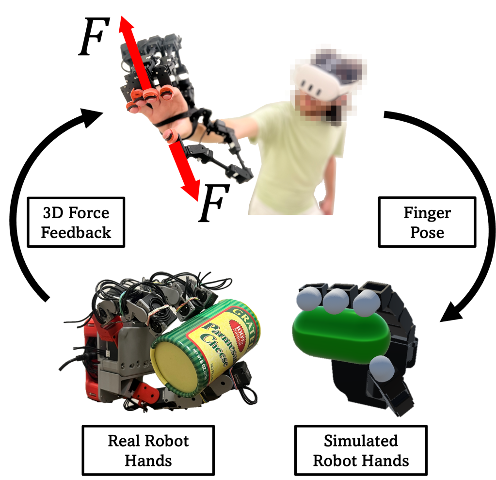
A: The APEX-Glove is a hand-wearable robotic exoskeleton. It’s made up of five small robotic arms (I call them “fingarms”) that both track and push on the wearer’s fingertips.
I built this device in 2025 to address a bunch of problems I saw in robotics and VR; lots of companies were building cool haptic gloves, but none of them produced 3D feedback (moreover, finger tracking wasn’t all that great…)
With everyone using teleoperation to collect humanoid robot manipulation data, it seemed insane to me that we expect robots to learn the intricacies of dexterous hand control when operators themselves are guessing what to do. Other projects like DexGen highlight this limitation pretty well, and even quote that teleop doesn’t scale too well because we need to FEEL and UNDERSTAND contact!
Hardware
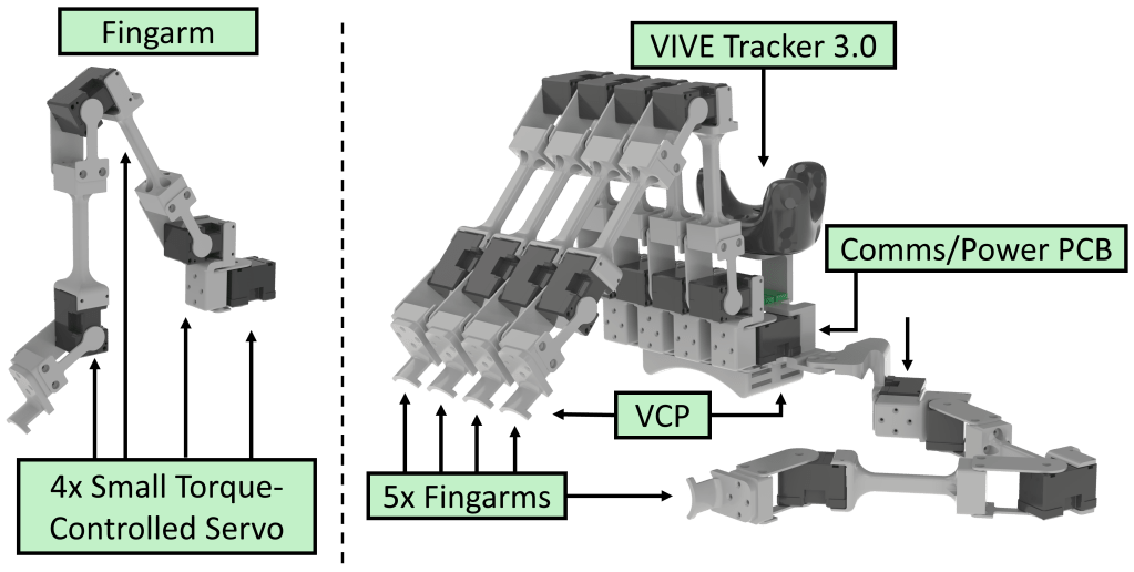
The APEX-Glove (right) is made up of 5x fingarms, with one attached to each finger. Each fingarm (left) is comprised of DYNAMIXEL actuators, bearings, and a bunch of 3DP parts (whose .3MF files are found below). DYNAMIXEL XL330-M077-T actuators are chosen for their relatively small size, low gearing, and current-control capabilities. The M288 variant has 4x the gearing, which results in ~16x the reflected inertia, which makes it feel WAY too heavy.
Relative to most other servos with plastic compound gearboxes, they’re pretty pricey at ~$25 USD/motor. The Feetech HL-3915-C001 seems like a cool alternative with metal gears, however, the lowered communication rate is a killer. This device needs the fastest whole-body communications it can get to work well… and for now, Dynamixels (4 MBaud) > Feetech (1 MBaud).
APEX-Glove Bill of Materials
| Part Name | Quantity | Cost [USD] | Link |
| Dynamixel XL330-M077-T | 20 | $549.80 | https://robotis.us/dynamixel-xl330-m077-t/ |
| ROBOTIS U2D2 USB-to-TTL Board | 1 | $36.92 | https://robotis.us/u2d2/ |
| 3P JST Exp. Board | 2 | $13.58 | https://robotis.us/3p-jst-expansion-board/ |
| 1 KG 3DP PLA Spool | 1 | $19.99 | https://us.store.bambulab.com/products/pla-basic-filament |
| Double-Sided Velcro | 1 | $8.99 | https://a.co/d/06T56lw4 |
| 5V/5A DC Adapter | 1 | $9.99 | https://a.co/d/0cJflrgC |
| M2 Screw Set | 1 | $9.99 | https://a.co/d/04eWr516 |
| MR115-2RS Bearings | 1 | $11.99 | https://a.co/d/0eXSPmjf |
| – | Total Price: | $661.25 | – |
3DP Part Files
The .3MF files for 3D printing can be downloaded from this link.
Inside are two folders containing 3DP files for Fingarms and the Chassis. You will need the following part quantity to build ONE Fingarm (for a full glove, you needed to do this FIVE TIMES.)
Each Fingarm uses modified Dynamixel actuators that replace the plastic casing with the “actuator_backplate” and an MR115-2RS Ball bearing. Additionally, each actuator also swaps the Dynamixel horn with an “actuator_rotor”. When coupled with the “actuator_idler” and the “actuator_bridge”, this forms a very low-friction, stable, and easily reusable joint module. From there, the links are used to form the full Fingarm.
Fingarm 3D Printed Part List
| .3MF file name | Quantity |
| link_0 | 1 |
| link_1 | 1 |
| link_2 | 1 |
| link_3 | 1 |
| actuator_backplate | 4 |
| actuator_bridge | 4 |
| actuator_idler | 3 |
| actuator_idler_splay | 1 |
| actuator_rotor | 3 |
| actuator_rotor_splay | 1 |
Following the build of your Fingarms, you will need the rest of the 3DP parts to build the “glove”.
These parts merely comprise the “ergonomic” parts of the build. What attaches to your hands, Fingarm placement, external sensors, etc.
APEX-Glove 3D Printed Part List
| .3MF file name | Quantity |
| mount_for_actuators | 1 |
| mount_for_electronics | 1 |
| mount_for_hand | 1 |
| mount_for_thumb | 1 |
| mount_for_vive | 1 |
From here, many M2 and M3 screws are used to fix everything together. You can reference the assembly guides below for further details.
Software
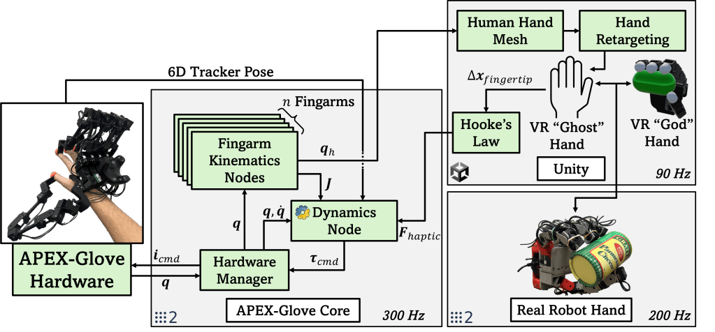
Figure 3 explains graphically (and a bit chaotically) how the APEX-Glove’s software works. Essentially, it functions as a distributed system using ROS2 on a network to connect different computers together. The “APEX-Glove Core” system directly interacts with the hardware via USB, and runs a bunch of nodes in parallel. Several nodes for computing forward and inverse kinematics (per finger), one for full-body dynamics, others optionally for calibration, etc. These interact with any ROS2 node that may take in human finger joint info (or send out force commands).
One such case is using the exoskeleton to control a robotic hand in the Unity game engine. Human finger joint angles are used to define a desired hand pose. The corresponding (real or simulated) hand tries to move to that pose. If it gets displaced by objects it encounters along the way, a force using Hooke’s law can be calculated (and displayed on the APEX-Glove). This super-simple implementation can work across any robotic hand, either simulated or real! Even better, it doesn’t require any special sensors at all; if your hand has joint encoders, that’s all you need.
In fact, this same process can be applied to human hand meshes for haptic VR as well!
Open-Source Code
**All of the open-source code will be posted to a Git server soon. It needs a refactor to be nice enough to work with 🙂 **
Everything is written in Python (the main bottleneck is USB to Device comms speed by far), with minimal dependencies outside of Pinocchio and ROS2.
Build Your Own!
** YouTube slicing, printing, assembly, and coding guides are coming soon! **
Theory
This section gives some additional insight into how everything works, without getting as technical as the research paper.
Finger Tracking
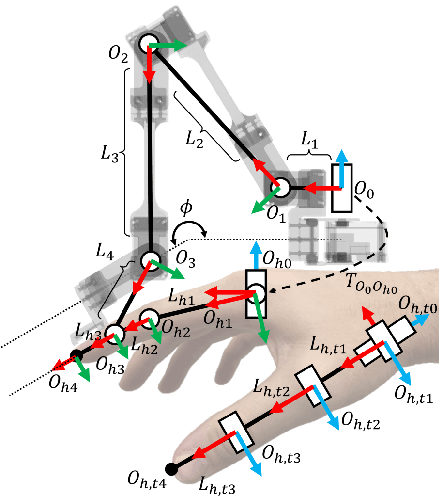
We use the Denavit-Hartenberg (DH) parameters of the fingarm to quickly and efficiently compute the robot’s Forward Kinematics (FK), giving us the position and orientation of the tip of both the fingarm and the user’s finger. From here, we can use Inverse Kinematics (IK) to compute human finger joint angles, working our way back to the wearer’s knuckles. The solution is closed-form and runs extremely fast (even in bad, human-written python), essentially meaning that finger position estimates are obtained with nearly 0 latency at extremely high sampling rates (approx. equal to the robot communication rate).
Dynamic Compensation
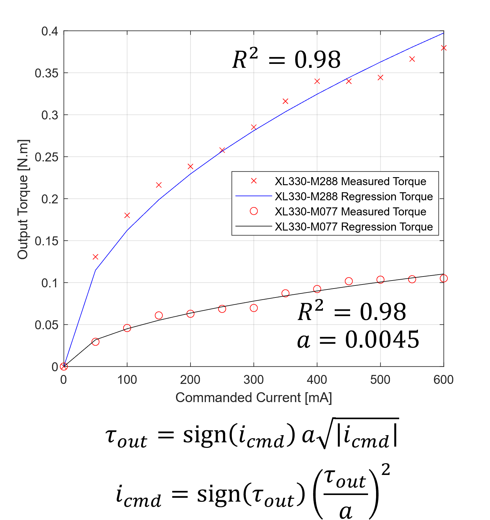
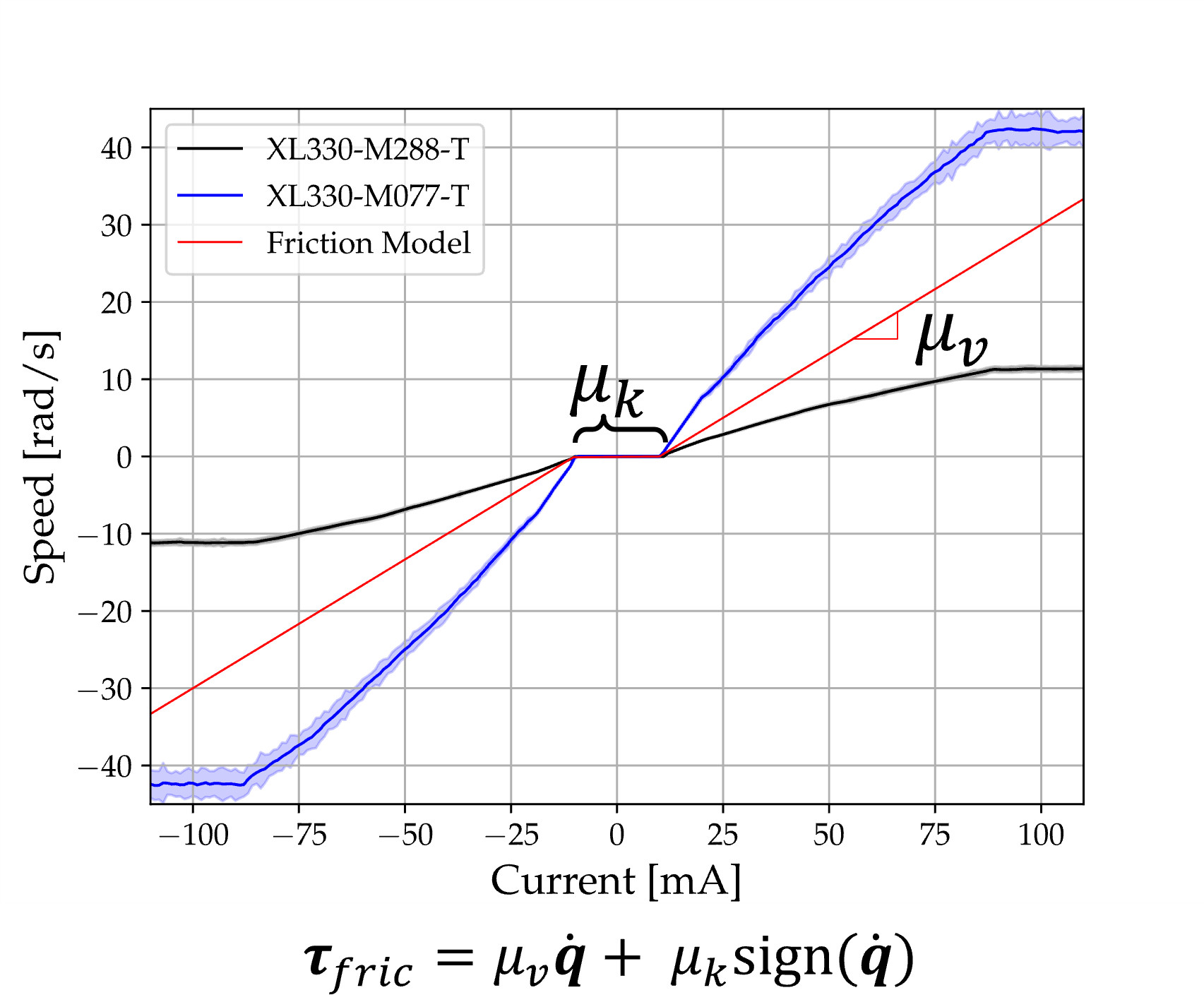
We use the Recursive Newton Euler Algorithm (RNEA) to compute joint torques needed to “cancel out” the weight of the links on the robot. To realize these torques, we use the current-torque model shown above (left), which I made through via data collection with a scale. This allows torque commands to be turned into current commands that the DYNAMIXEL actuators can produce. This allows us to also compensate for SOME joint friction via the model on the right, which compares input currents to the steady-state joint speeds they attain.
Force Control

Now that most of the (easily) compensatable dynamics have been accounted for, we can add the final joint torques necessary to render a desired force vector (tau_ext). The Jacobian of a fingarm is easily computed using the DH Parameters mentioned above. Furthermore, we use a “torque budget” to scale down the magnitude of this force to prevent actuators from saturating.
Known Limitations
- Finger tracking accuracy is EXTREMELY dependent on calibrating where the base of the fingarm is relative to the wearer’s knuckles in software. I have some tools to make this doable, but its pretty unintuitive. I think moving to known positions a priori and hill climbing to low RMSE could help!
- Force feedback magnitudes are pretty low overall.
- The device is really bulky, and can really only accommodate wearers with large hands (this is primarily due to the width of DYNAMIXEL motors…)
- The thumb fingarm’s placement could be improved… the better it aligns with the splay axis of a 4 DoF model of a human thumb, the better the overall performance will be.
- Feedback control with the device (such as pure Cartesian damping) is challenging due to the low overall control rate (300-400 Hz). Higher gains lead to instability, while lower gains produce too little force to be generally useful.
- A solution to this may involve splitting each Fingarm onto a separate UART, reconstructing the state of the robot internally, and sending that to the PC. This could lead to far higher (and more stable) speeds.
- Communication instability occurs at higher baud rates (2+ MBaud), which is really problematic for torque-level control.
- It is currently recommended to keep baud rates to 2 MBaud, which corresponds to a whole-body communication frequency of 300-400 Hz, assuming USB Latency Timers have been set to 0 a priori.
- The DYNAMIXEL actuators commonly overheat (not surprising since we’re operating near saturation).
- External tracking systems are needed to determine the gravity vector for weight compensation in arbitrary orientations. This adds extra weight and external dependencies, which can be cumbersome.
- A cube of April Tags on the back of the device might help with this… but that requires being in headset line-of-sight.
- The alternative is tossing a cheap IMU on board with Madgwick filtering, but that might need additional wiring or even onboard compute.
- The stack currently only supports external tracking from VIVE Tracker 3.0 and Meta Quest 3 Touch Plus. These devices pass orientation information to ROS2 via the Unity-ROS Bridge.
Future Work
- Make the device easier to manufacture and assemble.
- Stabilize communications further, attain higher communication rates.
- Switch to stronger motors with enhanced dynamic compensation, especially with joint inertia shaping. More transparency = more better 🙂
